
IO-Link – principles and technology
IO-Link is the world’s first standardized IO technology (IEC 61131-9) for communicating with sensors and actuators. The system components are an IO-Link master and an IO-Link device: a sensor, an actuator or a combination of both.
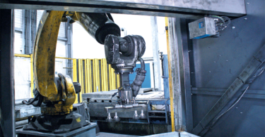
The master is a component of an I/O assembly either in the control cabinet or directly in the field as a remote I/O with an IP 65/67 enclosure rating. The device is coupled with the master using a standard sensor/actuator cable measuring up to 20 m in length. It produces and consumes signals (binary switching, analog input/output) that are transmitted directly via IO-Link in a digitized format.

Setting standards: IO-Link from SICK
- Serial, bidirectional point-to-point connection for signal transmission and power supply, no new bus system
- Backward-compatible with discrete standard PNP output sensors
- Operating modes: standard I/O mode (SIO), IO-Link mode
- Three transmission rates: 4,800 (COM 1), 38,400 (COM 2), 230,400 baud as an option (COM 3)
- Unshielded, standard 3-wire industrial cable for all connections
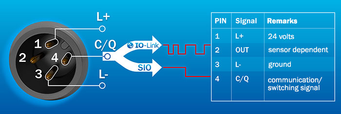
- M12 plug connector: 4-pin male connector for sensors, for example; 5-pin male connector for actuators, for example; 5-pin female connector for master
- Pin assignment: pin 1: 24 V, pin 3: 0 V, pin 4: switching and communication (C/Q)
- Maximum cable length: 20 m
- Maximum power consumption for power supply: 200 mA
- Process data (such as switching signals or distance values) is transmitted cyclically; service data (such as parameters) is transmitted acyclically
Need a refresher on the fundamentals? Check out the guest post by Comtrol, the North American IO-Link Competency Center: IO-Link 101: 8 Common Questions Answered or review the Glossary: 25 Important Terms to Know.
Watch the video below to learn more!
![]()