

Following are tips for the general synchronization of two LMS5xx scanners using SICK’s SOPAS software.Using SOPAS software, an LMS5xx PRO must be set to be Master only via Output 6 (master synchronization) and connected to a second LMS5xx through Input 4 (slave synchronization). On the LMS5xx, Lite Output 3 is used for master synchronization and SyncIN for slave synchronization. Using the Synchronization Phase value (range: –180…180°) in the SOPAS software, each Master-Slave link can be differentiated.
Wiring Connection
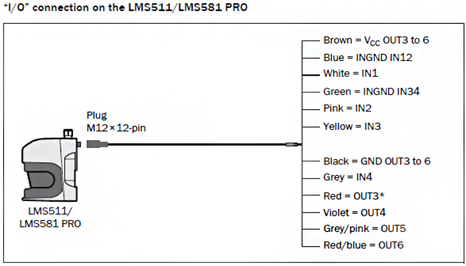
LMS5xx PRO Outdoor
Master: (I/O cable):
• brown (24V OUT3-6): to 24V
• black (GND OUT3-6): to GND
• red-blue (OUT6): to IN4 of the Slave
Slave: (I/O cable):
• green (GND IN3/4) to GND
• grey (IN4): to OUT6 of the Master
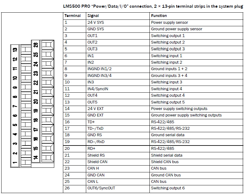
LMS5xx PRO Indoor
Master:
• terminal14 (24V EXT.): to 24V
• terminal 15 (GND EXT.): to GND
• terminal 26 (OUT6): to IN4 of the Slave
Slave:
• terminal 9 (GND IN3/4) : to GND
• terminal 11(IN4): to OUT6 of the Master
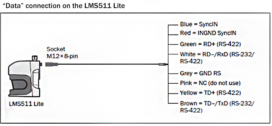
LMS5xx LITE Outdoor
Master: (I/O cable):
• red (24V OUT1-3): to 24V
• blue (GND OUT1-3): to GND
• pink (OUT3): to SyncIN of the Slave
Slave: (Data cable):
• red (GND SyncIN) : to GND
• blue (SyncIN): to OUT3 of the Master
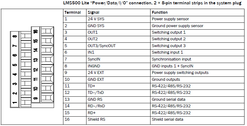
LMS5xx LITE Indoor
Master:
• Terminal 9 (24V EXT.): to 24V
• terminal 10 (GND EXT.): to GND
• terminal 5 (OUT3): to SyncIN of the Slave
Slave:
• terminal 8 (GND IN) : to GND
• terminal 7(SyncIN): to OUT3 of the Master
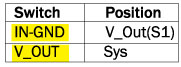
Yellow switches on the connection assembly
On the connection assembly of the LMS500, there are two yellow switches. Their position has to be as follows:
Parameters
LMS5xx PRO
Make sure that both devices are running at the same scan frequency.
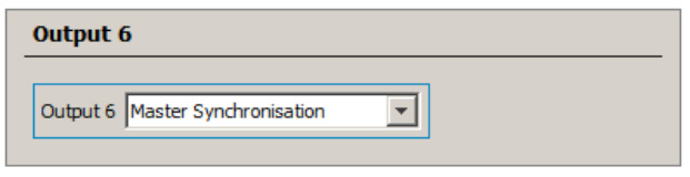
OUT6 of the Master has to be parameterized as Master Synchronization: Parameter / Network / Interfaces / IOs / Digital Outputs:
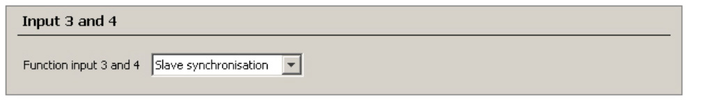
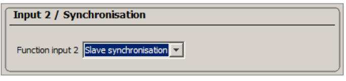
IN4 of the Slave has to be parameterized as Slave Synchronization: Parameter / Network / Interfaces / IOs / Digital Inputs:
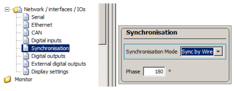
The phase of the slave can be freely parameterized between –180° … 180°:
LMS5xx LITE
Make sure that both devices are running at the same scan frequency.
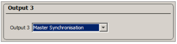
OUT3 of the master has to be parameterized as Master Synchronization: Parameter / Network / Interfaces / IO / Digital Outputs:
SyncIN of the slave has to be parameterized as Slave Synchronization: Parameter / Network / Interfaces / IO / Digital Inputs:
The Phase is to be done same as in the PRO, also the Master signal must look like in the example for the PRO above.
Sync Signal
The master delivers via OUT6 a rectangular signal, which starts with a rising edge at angle 0° and its period equals the actual used scan frequency.
The Master-Signal of the LMS200 for the synchronization is:
- high (+24V) from 0° – 180°
- low (0V) from 180° – 360°
For the LMS5xx it is the same.
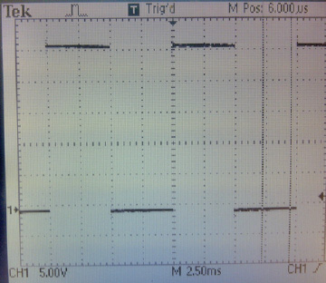
The output signal of the OUT6 of the Master must look like this if it is measured with an oscilloscope: (e.g., 100Hz scan frequency)
Using the Master scanner without any slaves is possible.
It could be used for a hardware signal to determine when the mirror is between 0°-180° or 180°-360°.
Sync by Wire / External Motor Synchronization
Feature available from V1.20 firmware on.
In V1.10, the monitoring of the external synchronization signal checked whether the connected signal was roughly in the right range. If this was not the case, synchronization was disabled and a ‘0’ displayed on the front panel of the device.
The actual allowable input frequency was only a fraction of this range and was set for ±0.1 Hz around the nominal frequency. This allowed two LMS5xxs to synchronize, but made it difficult to sync to an externally generated signal. Furthermore, it was possible that the LMS5xx could not sync, and did not flag this issue on the display.
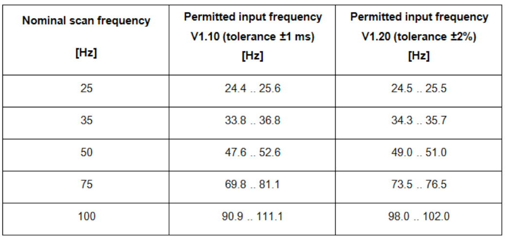
For V1.20 firmware, it provides for actual monitoring and the ability of the device match, i.e., the device is capable to lock over the full range of ±2% of the nominal frequency.
The current state of the external synchronization signal is displayed on the “Digital Inputs” page once “Slave synchronization” is selected:
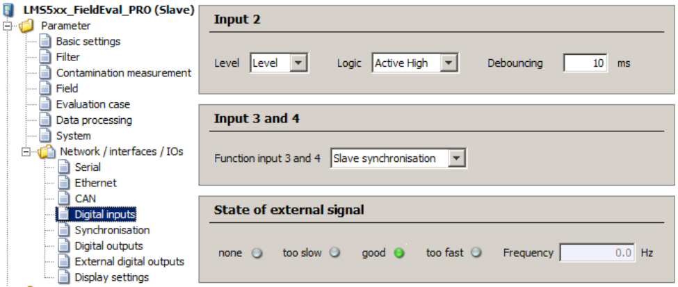
State of external signal:
none: no external signal detected
too slow: external signal detected, but below permitted input range
good: external signal within tolerance (refer to table above)
too fast: external signal detected, but above permitted input range
Sync by CAN
This is a SICK internal function, not to be used by the customer.
No Sync Signal at Slave (“0”on the display)
The Slave signals a ‘0’ on the display, sets a warning and deactivates synchronization on Slave, when:
– the period of the scan frequency of the Master is less than (period of scan frequency minus 1ms)
– the period of the scan frequency of the Master is greater than (period of scan frequency plus 1ms)
– no synchronization signal on the Slave is available
This could happen, when:
– there is a different scan frequency between Master and Slave
– heavy shaking of the device
– a synchronization wire not connected
Once a correct scan frequency of the Master is detected the Slave resumes synchronization, clears the display and removes the warning.
If Slave Synchronization is chosen and no cable is connected, no warning message is displayed.
A problem could also be, that the power supply for the output is not connected (Pin “24V EXT”: to 24V; Pin “GND EXT”: to GND)
Synchronization Signals for different synchronization phase values:

Possible wiring issues if it is:
![]()
– the GND In3/4 pin is not connected to GND (by the Slave); additionally double frequency by the Slave is shown
![]()
– no 24V on the Pin 24V Ext of the Master
– GND out 3-6 is not connected to GND of the Master
– Out 6 of the Master is not linked to the IN4 of the Slave
Limitations, Notes and Requirements of Synchronization
Maximum length of the cable between two scanners
Maximum line length is 15m.
Angle of Sync start and Period time
The signal goes by 0° from low to high. One Period of the signal equates exactly to one rotation, means e.g. 20ms at50Hz.
Slave = Master
A Slave can also be a Master and by this way is able to give the signal it received from his Master to the next slave. So it is possible to build up a line of several scanners where every Slave is Master for the next one.
Always pay attention, that the Signal of the first Master in the line may not be exactly the signal that is received by the last slave because of the internal processing time of every Slave/Master.
Signal tolerances
The synchronization frequency from the master LMS5xx has a tolerance of ± 2%
The max. and min. tolerance that the slave LMS5xx can accept is ± 2%
Mitigating electrical noise
Check the length of the cable. It should not exceed 15m from one scanner to the other.
The cable should be a shielded (our standard cables are shielded). The shield of the cable must be connected central star-like. The shield of the cable has connection to the housing or the device.
Take care about the correct connection of all GNDs of the particular scanner that may cause more of the noise. All GNDs should be connected in a star-like network.
Number of Slaves
Sync by outputs: One master is able to synchronize up to 6 slaves.
Sync by CAN: Reserved by SICK Inc.
Topology
Sync by outputs: It is possible to build up a star wired network of the scanners, or a line where every Slave is the master for the next slave (see chapter above).
Sync by CAN: As the scanner has only one CAN bus output, a star topology is not possible, because all Slaves have to share one single CAN bus.
Jitter of IN4
If an external synchronization is done via IN4, a delay in the timing can only come from the external signal device, because the internal timer for IN4 is very accurate.
Firmware version
All units must be Serial no. 1110 xxxx, or higher.