

Answering Your Questions about Physical Barriers as Addressed in Updated ANSI B11.19 Standard
Using physical barriers to separate individuals from danger zones is a tried and true means of reducing risk in the workplace. And though it may seem like a simple topic, there are many nuances associated with the various types of physical barriers that warrants a deeper look. In our recent webinar, we addressed physical barriers as a means to reduce risk and now we’re answering all your questions from that webinar. If you missed the webinar, you can still watch it here.
We spoke with Chris Soranno, SICK Safety Standards and Competence Manager, to get the inside scoop on physical barriers as addressed in the updated ANSI B11.19 Standard.
Are guards considered secondary to other engineering controls, such as control functions and devices?
Absolutely not! In the new edition of ANSI B11.19, one of the modifications made to the document was its structure and organization. As part of the revision, the various risk reduction measures were grouped according to the hazard control hierarchy (also referred to as the “three-step method” in ISO 12100). In the new structure, engineering control guards are listed second only to measures which are inherently safe by design.
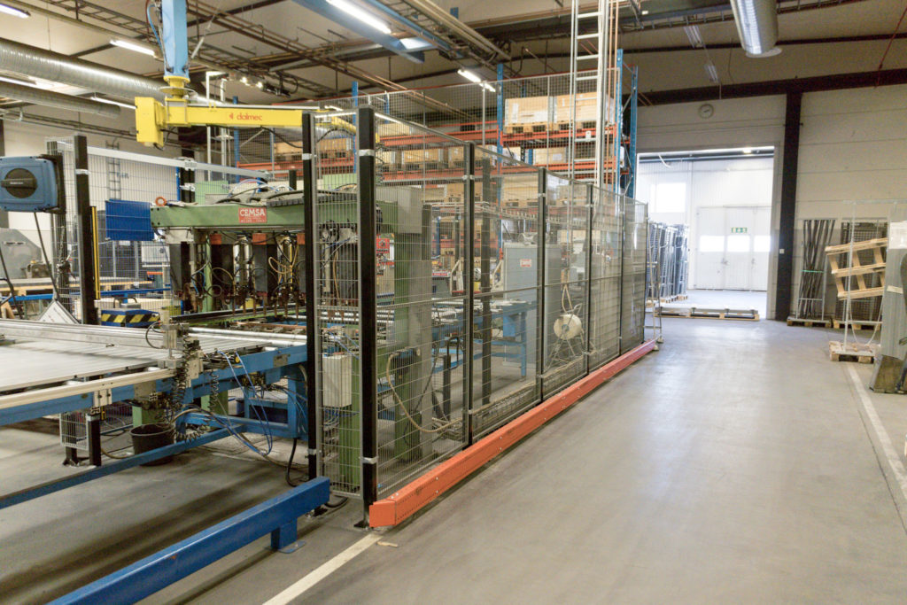
When exposure of individuals to hazards cannot be prevented through inherently safe measures, physical boundaries are the next best approach. Guards are often the first choice for risk reduction – especially to end users who cannot fully redesign existing equipment.
Physical barriers have been in use for the longest period of time due to their relative simplicity and proven effectiveness, making them the most common solution in industry. The relatively low complexity of guards and the extensive experience within industry explains why the applicable content in the new ANSI B11.19 is succinct and to the point (of the five categories of risk reduction measures in the new edition of ANSI B11.19, only 15% of the content is specific to guards).
Can we use hex nuts and bolts to fasten the fixed guard? Does every fastener have to be tamper-proof type?
ANSI B11.19 – as well as other industrial safety standards – require that the changes affecting risk reduction measures must only be made by authorized personnel. In practice, this means that all end users must have some level of control or supervision of the workplace.
To ease this burden, the standard states that “means to prevent unauthorized changes shall be implemented and maintained in a manner(s) that is effective and commensurate with the risk.”
One method of achieving this is to use hardware that requires a tool that is not readily available. In other words, if wrenches, plyers or other elements functioning as a tool to loosen/remove a hex nut is easily accessible in the workplace, additional measures should be considered.
Among many options, this may include:
- Designing guards with fasteners only accessible from inside the hazard zone
- Use of lock washers
- Use of special (so-called “tamper resistant”) fasteners; e.g. one way screws, pin-in Torx or Allen, etc.
- Welding / riveting connection points
Other example of means to prevent unauthorized changes are listed in Table 6 of ANSI B11.19-2019.
When can we use hand rails as a risk reduction measure, and when do we need to replace them with proper fixed guards?
As defined in ANSI B11.19, a guard intended to protect individuals from reaching the hazard must prevent access by reaching over, under, around, or through the structure. The intent is determined by a risk assessment; the higher the inherent risk, the more rigorous the requirements are for the associated risk reduction measure(s).
A guard is a barrier that provide protection from a hazard, and is considered more reliable on the hazard control hierarchy. A hand rail meets the definition of an awareness barrier because it warns individuals of a potential hazard by means of physical contact – but does not prevent entry toward a hazard. Due to their low effectiveness, they are near the bottom of the hazard control hierarchy, and therefore should only be used for low-risk applications.
Typical hand rails have a top rail at 42” (1066.8 mm) and a mid-rail at 21” from the walking surface, with intermediate vertical members no more than 19” apart (per OSHA 29 CFR 1910.29). To prevent reaching over a physical structure without additional engineering controls (e.g. presence-sensing devices), ANSI B11.19 (and ISO 13857) require a minimum height of 1400 mm (55.11”) – which is more than 1’ higher than a typical hand rail.
Both ANSI and ISO standards also state slotted openings more than 180 mm (7.09”) or square/round openings greater than 240 mm (9.45”) can allow whole body access through a physical structure. Based on typical handrail dimensions, openings in the structure can be as large as 21” (533.4 mm) high and 19” (482.6 mm) wide – clearly large enough for whole body access by reaching through or under the barrier.
How can we make a judgment for effectiveness of the partial guard/nip guard?
In both cases, partial guards and nip guards require secure attachment, and must be properly installed prior to operation of the equipment.
Nip guards have additional specific criteria which can be tested / evaluated to determine if the minimum requirements of the standard are achieved, such as:
- angle between the surface of the cylinder and the surface of the nip guard to prevent wedge pockets
- clearance between the nip guard and the respective machine part
- appropriate safety distance is measured from the hazard point of in-running nips
Partial guards, however, are more subjective in the fact that they must merely “limit access to the hazard.” The effectiveness of a partial guard must be determined by a subsequent risk assessment of the specific application to determine if the relevant risk factors (likelihood of avoidance and/or probably of occurrence of a hazardous event) have been positively affected by the addition of a partial guard. If necessary, awareness means (such as safety signs and/or color coding) may be useful to inform of the nature and location of the hazard(s) associated with a partial guard.
What should we do when we have some existing fixed guards that do not meet the 1400mm height and 180mm bottom opening requirements?
This is a common question, but unfortunately does not have a straightforward answer. On one hand, any non-compliance issue is an identified “gap” where an individual could be exposed to risk. On the other hand, if other machines exist in the workplace with NO risk reduction measures, one could argue that efforts should be applied where the highest risk is present.
A practical solution is to balance the level of inherent risk with the effectiveness of existing risk reduction measures. In other words, a high risk machine with some or most protective measures properly applied may not be as urgent as a medium risk machine with little to no measures in place. SICK offers a Machine Safety Prioritization Analysis service to level set these considerations and assist customers with the data collection and analysis to make well informed decisions.
You discussed interlocked guards needing to be located so that you cannot reach the hazard before cessation of the hazard when opened. Is there any accommodation for the length of time it takes to open the door and gain entry when determining the location vs. the stopping time?
When interlocked guards utilize devices with a guard locking function, the only applicable reaching distance considerations are related to the mechanical restrictions. In other words, reaching over, through and under the physical barrier as discussed. However, when using guard locking interlocks, the time to achieve a safe condition (a.k.a. stopping time) must be accounted for when determining when the guard locking device can be unlocked – via the safety-related parts of the control system (SPR/CS) – and allow access to the hazard zone.
The reaching distance considerations associated with the mechanical structure also apply when using a standard (non-guard locking) interlock device; but in addition, the response time of the system relative to the approach speed of the individual toward the hazard must ALSO be considered. This topic is addressed in the next white paper in the series, and will be addressed in the next webinar to take place in mid-September.
In most applications, access to the hazard is nearly simultaneous with opening the interlocked door (e.g., standing beside the door as it opens). Therefore, the time for the door to open ‘enough’ is typically not a deciding factor. Only in certain applications (e.g., a hinged door opening into a hallway of the same/similar width) will the opening of the door have an effect on the overall approach speed/time of the individual. A valid estimation of this time factor is extremely difficult to determine, with the exception of power-operated doors with a defined opening speed.
Can you talk more about the requirement for feedback (like an indicator light) to the person interfacing with the interlocked guard system?
As addressed in ANSI B11.19, awareness signals (which includes audible and visual signals) can be used as a risk reduction measure – often as a ‘layer’ used in conjunction with our measures. As with any risk reduction measure, selection / application is based on the results of a risk assessment, as well as any machine-specific consensus standards or company requirements.
As such, ANSI B11.19 does not require that operator feedback be provided. However, when visual awareness signals are used to reduce risk, the standard provides guidance on the characteristics of the signal (e.g., color, duration, amplitude/brightness, frequency, etc.) for proper application to realize reduction of risk.
More often, operator feedback is an element of ergonomic design guidelines intended to improve quality, performance and safety by reducing fatigue and injury. Many standards, including ANSI B11.TR1 on ergonomic guidelines, address the use of control coding/labeling and information display location/characteristics as a means to address cognitive and perceptual ergonomic considerations.
As used in the presentation, the indicator light icons were intended to highlight the status of the machine control system (stop/ready/go) relative to the logic conditions. In turn, this can reduce cognitive and perceptual fatigue in the workplace, which often result in other more serious injuries and incidents.
Risk assessments are to be done without guarding included. How, or when, do you consider risks introduced by the guarding itself?
This is correct; the risk assessment process begins with an evaluation of the inherent risk present on a machine or system. Following identification of all tasks and hazards, the risk factors (severity and probability) are estimated assuming no risk reduction measures (such as guards) are present.
When risk is determine unacceptable, risk reduction measures are then applied. Throughout the application of the risk reduction measures (following the hazard control hierarchy), the risk assessment process is completed iteratively to determine when tolerable risk has been achieved. As part of this iterative analysis, each risk reduction measure is evaluated for its effectiveness toward reducing risk, and should also be evaluated to determine if any new risk(s) have been introduced. In the case of physical barriers, typical examples include:
- new crushing, shearing or in-running nip hazards introduced by decreased clearances;
- new cutting or abrasion hazards introduced with rough edges;
- new cognitive hazards introduced by lack of visibility.
Do you think ANSI has now caught up to ISO?
Standards are always evolving based on current best practices and lessons learned. In the case of ANSI B11.19, great effort was taken to closely examine differences with other similar standards in the global marketplace. As it relates to the specific topic of physical barriers, the new (2019) edition of ANSI B11.19 has come the closest yet to aligning with requirements of international standards, such as ISO 13857.
However, alignment was made where justified; in some instances, it was acknowledged that new approaches or different considerations may warrant deviation from other guidelines. In those instances, efforts are being made to bring the approaches from ANSI B11.19 to those other groups of technical experts to determine if additional alignment can be made in the future.
Can a movable barrier device be used as a full pallet exit since it could allow for full body access?
This is dependent upon the application. If the configuration of the equipment is such that a full pallet can exist the safeguarded space, yet an individual cannot enter, then it is possible. An example would be if the conveyance system is elevated from the walking/working surface of the individual at a sufficient height to also act as a protective structure.
If this is not possible, the considerations for whole body access should be reviewed, as discussed in a previous white paper and webinar in these series.
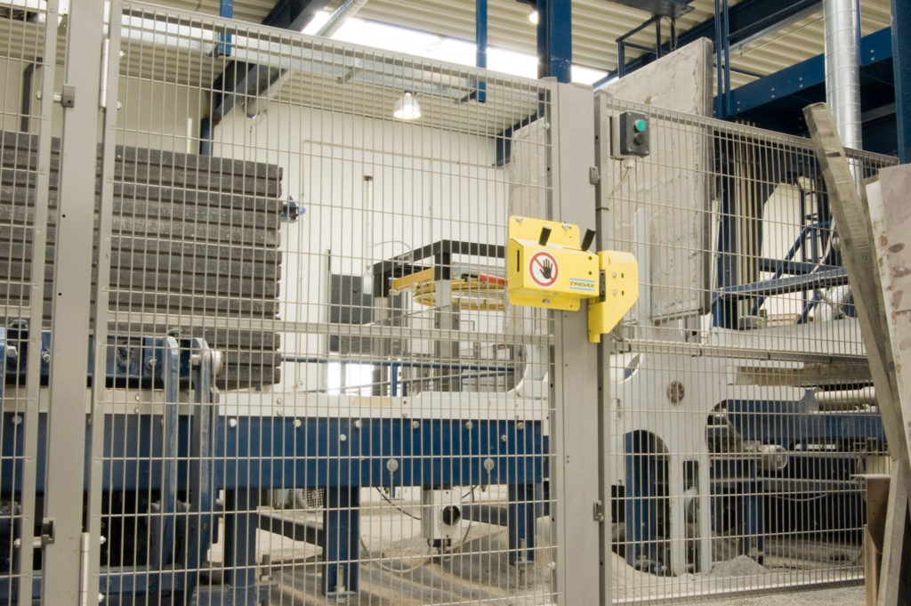
Should a moveable barrier device have a PLr?
By definition, a movable barrier device must be interfaced into the machine control logic (typically with an interlock device) in order to actuate the next machine cycle. When the movable barrier device is used as a risk reduction measure, that specific portion of the machine control function is now a safety-related part of the control systems (SRP/CS). Additionally, the measure would also meet the definition of a “safety function” (function of a machine, the malfunction of which would increase the risk of harm). As such, the considerations of functional safety would then apply, and the overall performance of each safety function must be commensurate to the associated risk(s) the measure is intended to reduce.
In consideration of a flexible guard (e.g. a hanging rubber curtain), can it be considered a guard, perimeter guard, or more of awareness means?
ANSI B11.19 establishes minimum performance criteria for each of the different functions physical barriers can fulfill when used for reducing risk to individuals. Additionally, each barrier must be evaluated based on the task/hazard pair(s) it is intended to address. If a hanging rubber curtain is used only to keep hazards (such as noise, exhaust, or swarf) away from individuals, then it could possibly be considered as a “shield.” However, if it is used to prevent individuals from accessing a hazard zone by reaching around, under, through or over the barrier, additional requirements apply before it will fulfill the conditions of a “guard.” If the barrier provides only simply contact to an individual, but does not prevent access, additional training must be provided in order to fulfill the requirements of an “awareness barrier.”
Therefore, each specific application must be evaluated to determine how a physical barrier functions, and if it achieves the desired degree of risk reduction.
When scoring risks after guarding, is it likely that Degree of Possible Harm and Frequency of Exposure are reduced?
Accurate estimation of residual risk is a key element of a successful risk assessment/risk reduction process. Fortunately, the general safety standard ANSI B11.0 includes an informative appendix (Annex A) which includes a table listing potential effects of risk reduction measures (see Table 6 in the new 2020 edition). According to the guidance of this consensus document, fixed guards may be able to reduce frequency of exposure and/or probability of occurrence. However, a thorough evaluation of each specific application is necessary before any final evaluations can be made.
You spoke about interlocked guards and what needs to be considered when accessing a hazard zone. Are there any special considerations to be made when a person is inside a hazard zone and needs to come out?
When a person can enter and be completely inside the risk reduction measures defining a perimeter or safeguarded space, the situation is referred to as “whole body access.” The new edition of ANSI B11.19 now includes an entire clause (9.11) addressing the various approaches which can be applied to effectively reduce risk. This section includes requirements for the interlocking device (including guard-locking interlocks) as it relates specifically to the ability to escape from a hazard zone. When this approach is used to address whole body access, an initiation warning system must also be applied to notify the individual with sufficient warning that they must exist the area.
The topic of whole body access is quite detailed and includes many other considerations as well. These have been discussed in a previous white paper and webinar in these series.
What would be considered a protected polycarbonate? Does the curve change if the polycarbonate is protected? And by protected, does that mean there is a coating of some sort?
The presentation briefly showed an aging curve of unprotected polycarbonate with averaged test points (Figure G.1 in ANSI B11.19-2019). In turn, this data came from ISO 23125 (international safety standard for turning machines), which drew upon other published studies.
The data presented by manufacturers is often expressed as the impact strength of the polymer and determined by test in a research application. The associated text in Annex G acknowledges that various manufacturers may incorporate additives and coatings that can affect the properties of the panel. In some applications, multiple layers with additional protective coating(s) may be required to sufficiently address a polycarbonate material from exposure of degrading environmental influences. An informative note warns that care should be exercised when attempting to extrapolate the results to other materials (e.g., acrylics, glass, PETG, CAB, etc.).
So in essence, the curve shown is an example of decreased impact resistance over time; other materials (or additional layers / coatings) may improve the data results.
 ANSI B11.19 White Paper Series
Want to learn more about the updated ANSI B11.19 standard? Read our white paper series to learn more: part 1, part 2, part 3, part 4, and part 5. Also, don’t forget to watch our webinar on physical barriers to learn more!