

Get the most from a SICK’s LMS sensor by minimizing errors. The devices may sometimes emit a systematic or statistical error, which influence the scanner's measurement accuracy. Depending on those values, the accuracy of the sensor can be calculated using the maximum of both measurement errors added together.
There are two ways to minimize measurement errors. One possibility is within the device itself. Another method is in the software through a calculation process.
Outlined below is the best way to minimize these errors.
Device properties
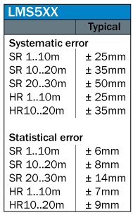
Measured values differ from sensor to sensor. For LMS5xx sensors, it also depends on the distance to the sensor and the variant of this sensor class.
Values LMS1xx
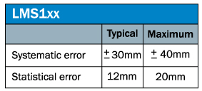
The measurement error of the LMS1xx is about 23 mm at a distance of 1 m. It increases if the measurement distance is lower or higher.
Values LMS5xx
Definition of error types
Statistical error
The statistical error means that when the sensor performs several measurements, it will not output the same value every time. This is similar to when a measuring tape is used to measure two points several times, the result may not be exactly the same value every time. To minimize the statistical error, the easiest way is to obtain several measurements together and build a mean value over these scans.
Systematic error
The systematic error depends on the measurement principle, and on the construction of the scanner. It also depends on the temperature. It is not possible to eliminate this type of error completely, but there is a way to minimize the influence of this particular error.
Minimize the statistical error
Mean filter in the LMS
SICK's LMS has a filter called a “mean filter.” When this filter is activated, a number of scans can be parameterized. These scans are taken together and from that, a mean value from every scan degree over all the scans will be calculated. Then, one data string is given out with these mean values. This also implies that there is a reduction of data throughput, because only every 10th or 100th scan is provided. To eliminate the statistical error, a recommended number of scans is 100.
Mean filter in a processor
A similar process that is used with the embedded LMS mean filter can also be done in an outboard processor, please see the text above.
Floating mean filter in a processor
With a processor, a floating mean value can also be programmed. Therefore, always take the actual scan. Then for the mean value, take the necessary amount of scans as before, and calculate a mean value. With the next scan, take the actual scan and the same amount of scans as before and do the same calculation. In this manner, you will get more values, but a mean value is the result anyway. This means you will obtain every scan, and the data amount is not reduced.
Minimize the systematic error
Take a reference point from which you know the exact distance to the sensor. It should be a point that never changes position and distance, relative to the sensor, and is always detectable. It should not be in the area where actual object measurement occurs, in order to avoid objects that may cover the reference target. Our reference point should have a minimum distance of 0.5 m to the sensor. Below 0.5 m, the measurement values of the scanner are not guaranteed to be close to rated specifications.
That is why the use of the scanner is recommended starting from 0.5 m distance to the objects.
It is best is to mount the target perpendicular (90°) to the reference scan beam, so that most of the sent laser light will return to the scanner, and will not be reflected anywhere else. Also, a good surface of the reference target is important. Black and shiny surfaces are not ideal. White paper, for example, is fine. The best alignment of the reference target is a vertical mounting, so that no dust or dirt settles on the target. As a result, reference measurements are optimal when using this mounting configuration.
Be sure to note factors that can influence the result such as a bad position of the reference target (too close to the scanner), good measurements are not possible below 0.5m; or if the target is not in 90° to the scanner. In this case, light might be reflected away and is lost for the measurement.
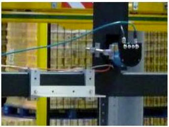
Good position of the reference target(more than 0.5 m away, in nearly 90° to the scanner):
In every scan, this reference point is measured and the difference from the actual measured value to the real distance value of the reference point can be calculated. In the following calculation of the measurement values, the processor can take the difference between the actual measured value to the real distance value into the process. If the reference target is measured further away than it is in reality, subtract the difference from all following relevant measurements. If it is nearer, add the difference to the measurement values. Leave the mean filter on, so that the statistical error is already cleared when the reference measurement is done.
Example 1:
Real distance of the reference target (measured by real accurate method):
1.53 m
Measurement value in the scan from the LMS: 1.58 m
Difference: 0.05 m –> too far
Every measurement in that actual scan must be adjusted: angular measurement value – 0.05 m
Example 2:
Real distance of the reference target (measured by real accurate method):
1.53 m
Measurement value in the scan from the LMS: 1.50 m
Difference: 0.03 m > too short
Every measurement in that actual scan must be adjusted: angular measurement value + 0.03 m
For reference target selection, use a non-reflecting surface. It should not be shiny and have good remission. It is best to use a white target.
Please contact autoidhelp@sick.com for more support on this topic.