

This is a guest post from Axis Inc., an Authorized SICK distributor and engineering firm in New Jersey and Metro NY, specializing in motion control, machine control, machine vision, and process automation.
Ultrasonic Sensors Background
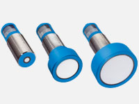 SICK ultrasonic sensors are used to determine the distances from an object, using sound pulses to send and receive signals. The time it takes for the ultrasonic sensor to send and receive the signal determines the distance. A major benefit of ultrasonic sensors is the fact that they can detect distances to clear objects and clear liquids.
In this post, we’ll show you how to send an analog output to the UM30 using Connect+.
Programming
Step 1: Connect the SICK programming device into power and to the ultrasonic sensor
Step 2: Connect the USB end into your computer.
Step 3: After all connections are made open your Connect+ software tool.
Step 4: You will then see the following screen. Click the read parameter from sensor tab located on the top left.
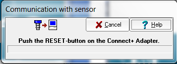
Step 5: Once this image pops-up, press and hold the R button on the SICK remote programming device. The remote will display text “3-2-1… Reset”
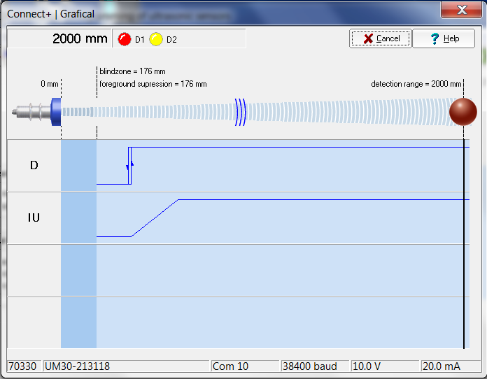
 Step 6: After completing the reset stage, the page below will appear on the screen. You will notice on the top there is a blind zone and a foreground suppression.
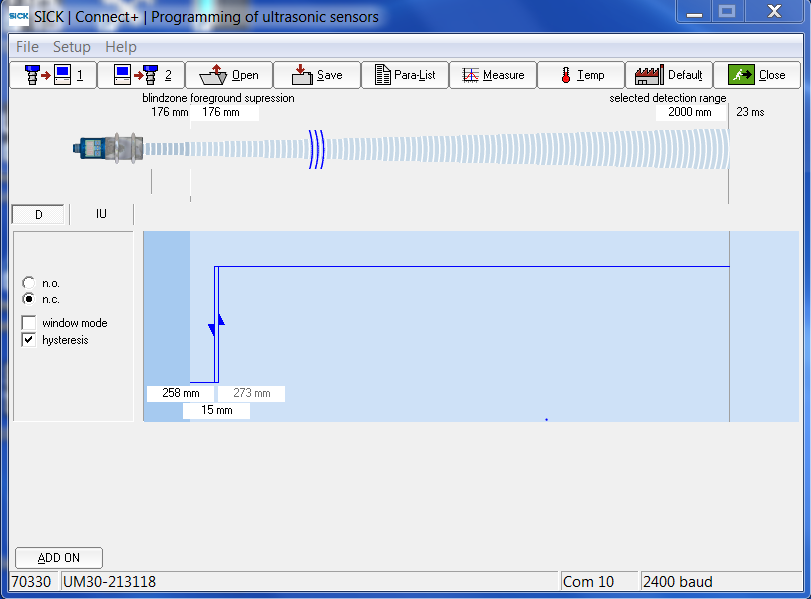
Any object that you want to detect must be past the blind zone. This is because the pulses that the sensor is sending and receiving are too strong at this distance. With this particular sensor, once the object is further than 176mm, the distances can be measured accurately.
The foreground suppression represents an artificial blind zone, therefore the measurement readings will not be displayed until the object is further than the set distance.
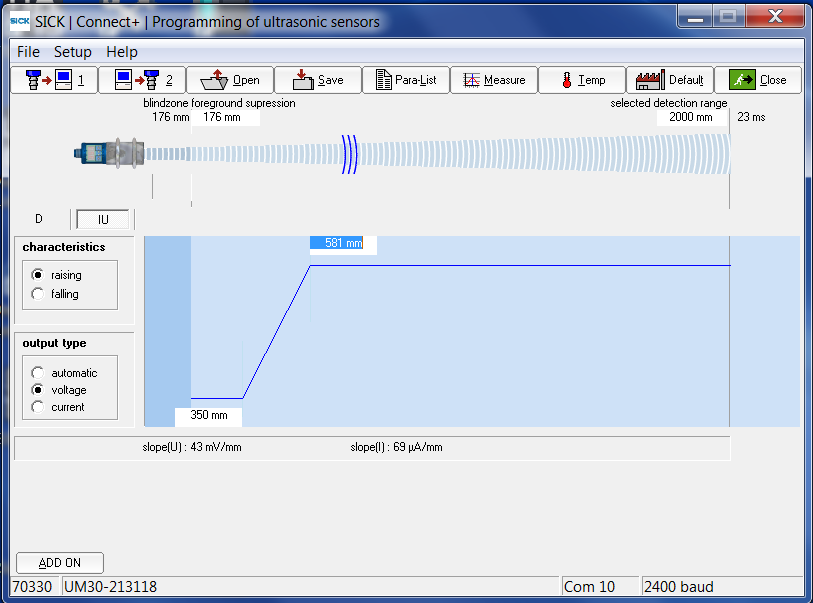
Step 7: To have the sensor send analog output, the user must click the IU tab. On this page you can choose the range of 0-10V or 4-20mA. For this example we will use 0-10V. In the image below you will notice two numbers on the blue screen, they are 350mm and 581mm. This is the 0-10V range. Any reading below 350mm will read 0V and any number higher than 581mm will give a reading of 10V. As well as any number in between will move proportional to the distance.
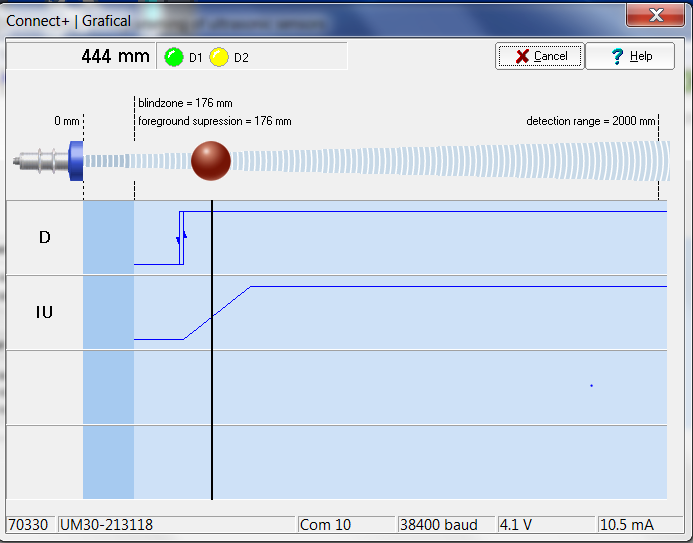
Step 8: Click the measure tab at the top of the window. Which will bring you to the window below. Click the “graphic” tab.
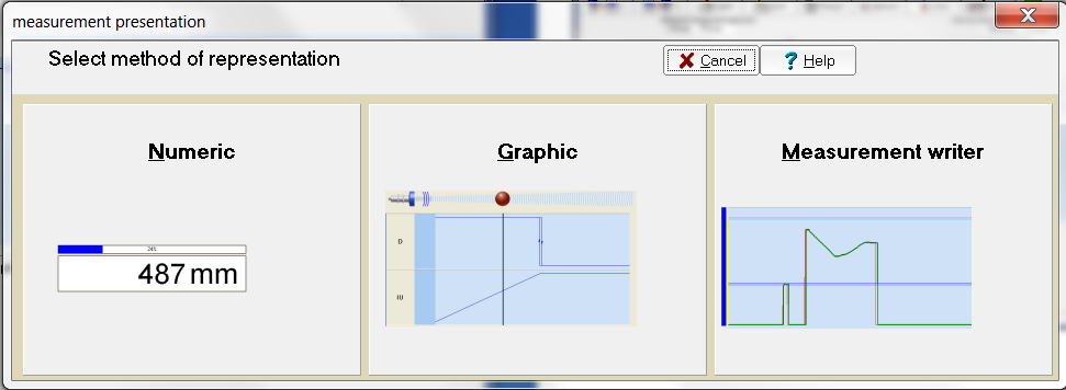
Step 9: On this page you are shown the digital and analog signals from the sensor. The bronze colored ball represents an object in the field of view. Here, the object is located beyond the detection range, therefore giving an analog output of 10V. Shown on the bottom right.
Step 10: When the object is located at a distance between 350mm and 581mm, it will send an analog output of 4.1mm.
TIP: If you are trying to determine distances that are very close in distance, create an analog window that is smaller. For example if you are looking at objects that are 380mm to 383mm in distances and want a different signal for each. Set the window for 375mm to 390mm.