
Why use the Inspector Vision Sensor?
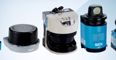
T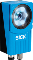 he ability to integrate a vision sensor like the Inspector into a factory automation setting provides a level of quality control that was often previously delegated to manual inspection. Transitioning to automated inspection of an object during the manufacturing process improves quality and reduces waste.
In North America, one of the controllers most often implemented in factory automation uses EtherNet/IP to gather data from remote devices like our Inspector vision sensor. Follow the simple steps below to see how you can configure the Inspector to transmit its data to the controller over EtherNet/IP.
This is an overview describing how to get data from an Inspector PI50 or PIM60 vision sensor into a Rockwell Automation PLC over EtherNet/IP.
First Steps
Before beginning, please note that the Inspector has already been taught a reference image and the tools required to make an inspection have been applied to this image.
The screen captures below show SOPAS Single Device V2.38.3 and RSLogix 5000 V20. The vision sensor used in the following example is the Inspector PI50 (the setup of the Inspector PIM60 is identical) and the Rockwell Automation PLC used is the ControlLogix.
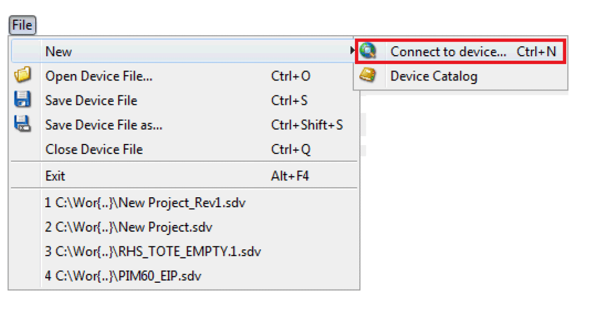
In SOPAS Single Device there is a ‘Connection Wizard’ that will guide you through the setup of connecting to the Inspector PI50 using Ethernet TCP/IP.
Once connected to the PI50, SOPAS will display the main screen showing a LIVE image from the sensor. Adjust the sensor so that a sharp image appears (an image sharp and clear enough to show good contrast between the target object and the background). A good reference image allows you to apply the tools required to perform the desired inspection. Click on the “Run” button to download to flash.
The SOPAS screen should look like this:
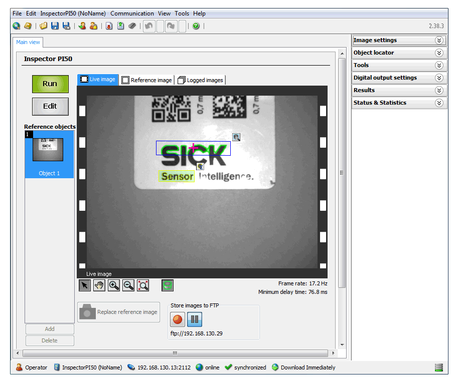
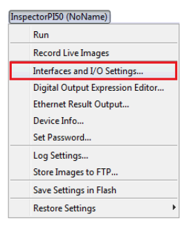
To configure the PI50 to transmit its data to the ControlLogix, it needs to be setup to communicate EtherNet/IP. Put the PI50 into ‘Edit’ mode and select the dropdown menu under “InspectorPI50 (NoName).” Select “Interfaces and I/O Settings…”.
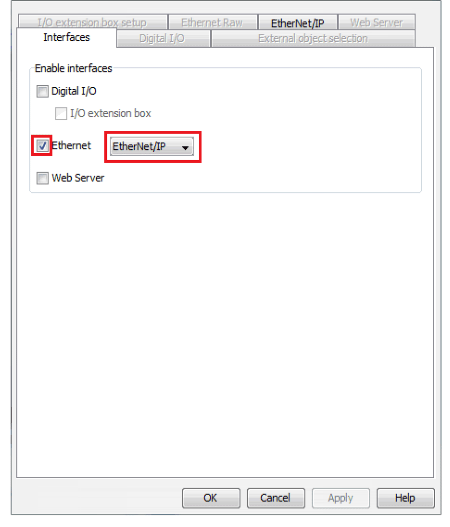
The properties window for “Interface and I/O Settings…” will appear. In the “Interfaces” tab, select Ethernet and in the dropdown menu select “EtherNet/IP.”
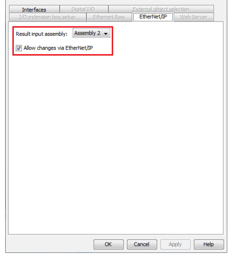
The “EtherNet/IP” tab should now be available. From here you can access the EtherNet/IP properties. This enables you to set the Assembly (this dictates how much data the PI50 will generate) and whether you will allow for changes (primarily triggering) over the EtherNet/IP network.
NOTE: There are four assembles to choose from: Assembly 1, 2, 3, and 4. Their sizes and Input Assembly Instances are different. The assembly is chosen based on the reference image with the most tools. The more tools, the larger the Assembly size required.
Once an Assembly is chosen, click on “Apply.” Then click “OK” to finish and close the “Interfaces and I/O Settings…” window.
Next, the data from the PI50 for the reference image needs to be validated. Again, pull down the menu for the “InspectorPI50 (NoName)” and select “Ethernet Result Output….” Choose ‘Create example formatting string’ and then ‘Validate output string.’
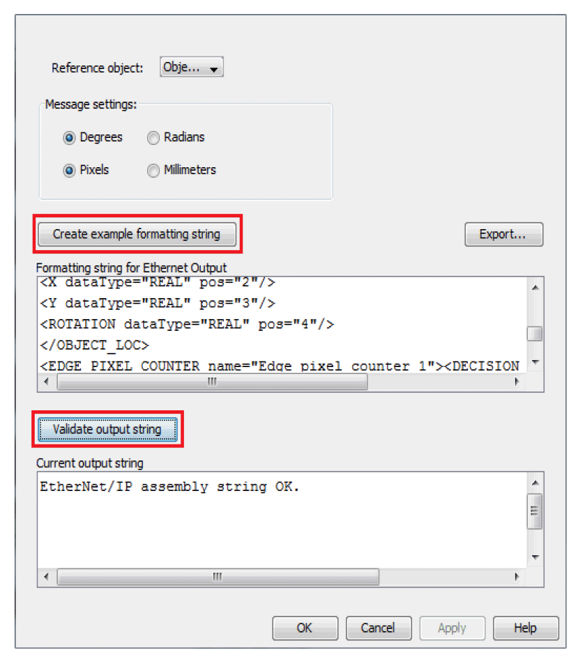
If the string validates “OK,” click on the “Export” button to save a copy of the output format. This copy will be used as a guide to tell you where the data for each tool will be in the Input Tag Database in your PLC.
After you’ve saved a copy of the output format, click on ‘Apply’ then ‘OK’ to close the window.
At the main SOPAS screen, click on the ‘Run’ button to save this configuration to flash.
The PI50 is now setup to communicate to the PLC over EtherNet/IP.
Now the PLC needs to be setup to receive data from the PI50. With RSLogix 5000, set up your system within the ‘I/O Configuration.’ Add your local I/O and communication interfaces to the chassis. For your communication interfaces you will need to add the clients/slaves to the respective communication interfaces.
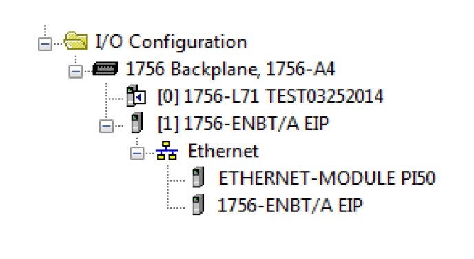
The PI50 should be added to your I/O Configuration as a ‘Generic Ethernet Module.’ For the purposes of this example, the PI50 is configured with these properties.
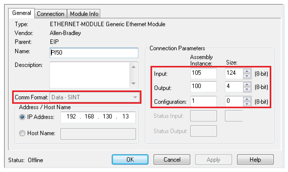
The data from the PI50 is SINT. The connection parameters are based on the assembly size selected during the setup of the PI50 using SOPAS (see above). The example uses Assembly 2, which corresponds to an Input Assembly Instance of 105 and a data size of 124 Bytes.
NOTE: Regardless of the Assembly used (1 through 4) the Output Assembly Instance will always be 100 with a size of 4 Bytes.
The rest of the information will be based on how you have the PI50 configured on your network (i.e., IP address) and whatever makes sense to you in your program or application (i.e., Name).
Clicking on ‘Apply’ will take you to the ‘Connection’ tab. Make sure you have the “Use Unicast Connection over EtherNet/IP” selected.
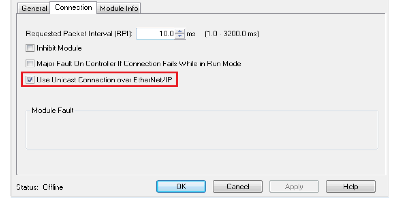
Click on ‘OK’ to complete the configuration of the PI50 within your PLC. Once this is completed, the configuration can now be downloaded into the PLC.
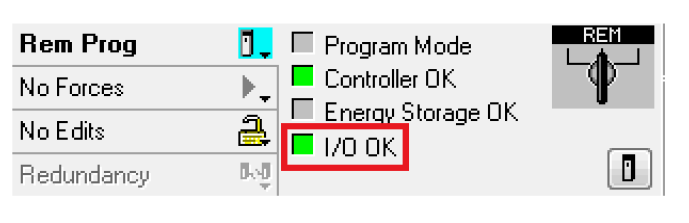
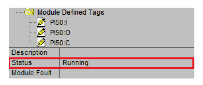
The module diagnostic window for the PI50 should show this:
The PI50 Input, Output, and Configuration Tags can be found in the ‘Controller Tags’ within the RSLogix 5000.
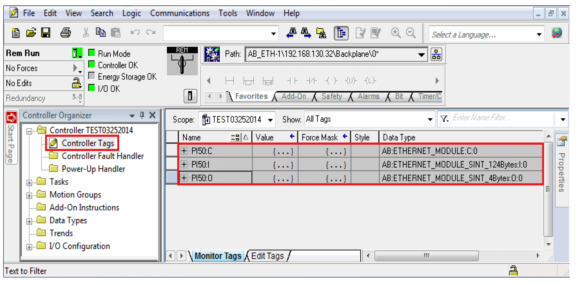 Expanding upon the PI50 Input tag database you will get 124 Bytes of SINT data.
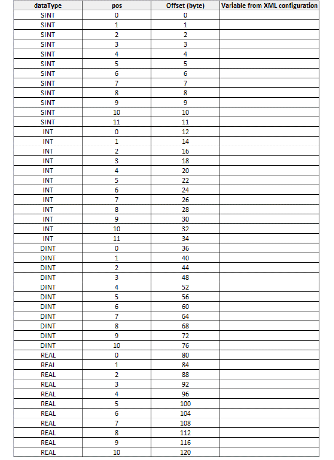
The PI50 actually generates SINT, INT, DINT, and REAL data (in this order). However, when setting up the PI50 as a ‘Generic Ethernet Module’ only one data format can be used (SINT). So how much of each type is generated is critical. This table details the data format for Assembly 2.
Where:
SINT = 1 Byte
INT = 2 Bytes
DINT = 4 Bytes
REAL = 4 Bytes
One of the steps above was to ‘Export’ the PI50 output format after it was validated. This XML file is used to indicate where the data is located for each tool configured for the reference image within the PI50.
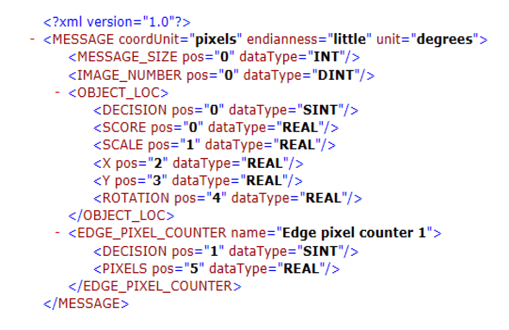
Based on this output format, the data would appear like this:
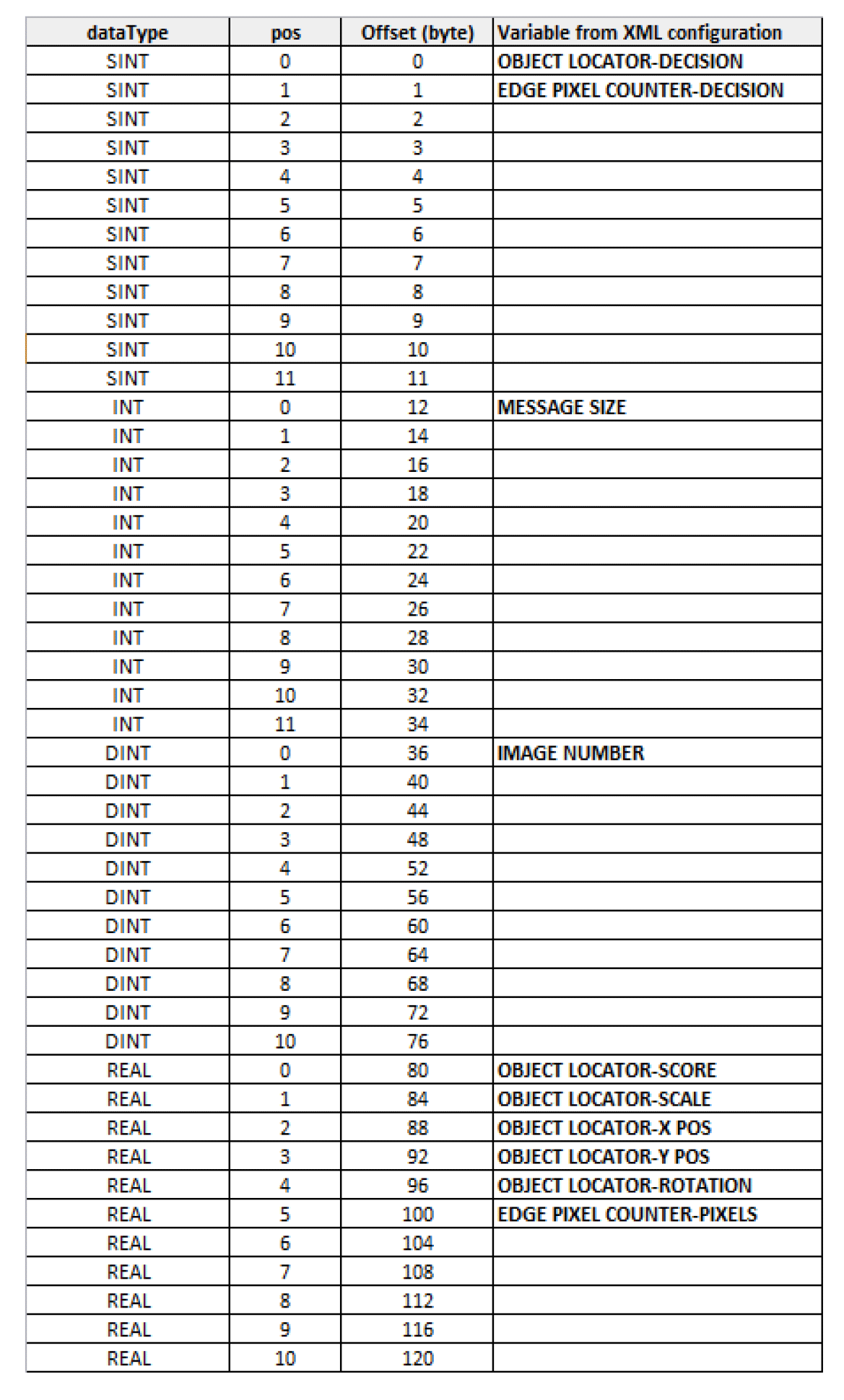
To associate the data in the above table to the input tag database in the PLC follow the “Offset (byte)” column in the above table as this will indicate where the corresponding data appears in the tag.