


 Once you’ve determined that an Inspector vision sensor is the appropriate solution for your application, there are certain considerations to make regarding how it is triggered. Is it necessary? And if it is, how will it be triggered? Depending on the application, triggering, particularly over Ethernet, can be very beneficial.
Why Trigger your Inspector?
When the Inspector is triggered, you are guaranteeing that only useful images are being processed. In contrast, when the Inspector is in free-running mode, it is constantly analyzing images, so it is possible to miss a useful image because the processing of a useless image prevents the capture of a useful one.
Okay, But Why Trigger over Ethernet?
Triggering an Inspector using a sensor input can be very simple, but it might not always get the job done. If an accurate count of triggers must be maintained, a PLC may need to be used. This can be done by triggering the PLC with a sensor or a timer if the application is consistent enough. If the Inspector only needs to be triggered after an event that doesn’t involve a sensor input, using a PLC and Ethernet is a reliable option.
Furthermore, if more than discrete outputs are needed from the Inspector, the data will need to be communicated via Ethernet. This configuration is identical to the one needed for triggering over Ethernet, which is highly convenient for initial programming of the vision sensor.
Alright, I’m Convinced. But How Do I Do It?
Setting up the Inspector so it is triggered over Ethernet is very simple. In this example, we will be using TCP/IP.
Before starting, you will want to be connected to your Inspector via your host. If you are planning on sending data from the Inspector to your host via Ethernet, set up your reference image(s) as well.
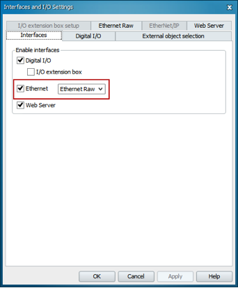
1. Enter into the Inspector’s Interfaces and I/O Settings (found in the menu bar under InspectorPIM60). Enable Ethernet, and select Ethernet Raw
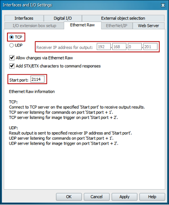
 2. Go into the Ethernet Raw tab and enter in the IP Address of the host and 2114 as the start port. Select TCP for the communication. You may not be able to edit the IP address of the host when TCP is selected. Click OK to save the settings and close the Interfaces and I/O Settings window.
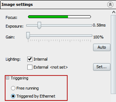
3. Under Image settings, select Triggered by Ethernet.
4. At this point, the Inspector is ready to be triggered over Ethernet. To customize the output string, open the Ethernet Result Output window (found in the menu bar under InspectorPIM60). You can either create a string of your own or use the sample string automatically generated. Check to ensure the string is valid and hit OK to save the settings.

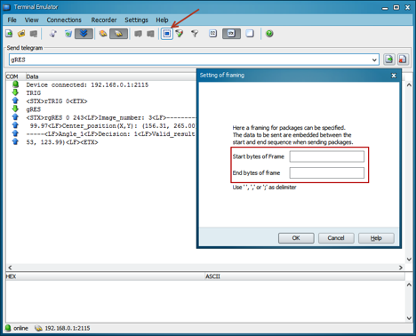
5. To test the triggering, open the Ethernet terminal emulator of your choice. Connect to the device using the vision sensor’s IP address. By default, the Inspector is a 3-port device. Port 2116 is used to send data from the Host to the Inspector, and port 2114 is used for sending data from the Inspector to the Host. Port 2115 can be used as both; however, because it is both sending and receiving data it may take longer to transfer. Additionally, a request for the return data must be sent.
To trigger over 2116, use the command TRIG. No command is needed to receive on port 2114.
To trigger and receive over port 2115, use the command TRIG to trigger and gRES to receive the result.
6. Be sure to remove framing on the outgoing data before triggering, as shown below. Failure to do so will result in an error.
If you have additional questions once your Inspector is triggered, please contact info@sick.com.
Your Turn…
How has triggering your vision sensor proved beneficial for your applications? Tell us in the comments below.
[custom_author=Haya Bashir]