


This post illustrates step-by-step instructions for operating the Visionary-T 3D vision sensor, including how to establish height reference, how to measure objects, and how to determine the object resolution of the sensor.
This post is not meant to replace the Operating Instructions for this product.
 How to Establish Height Reference
The following instructions show you how to establish the height of the scanner from the center of the lens to the floor. This will serve as a reference point for future measurements.
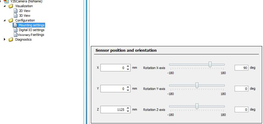
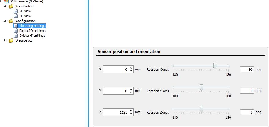
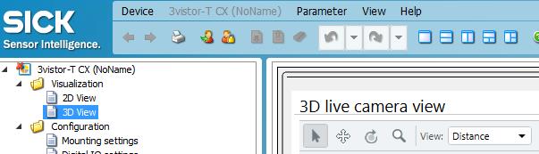
1. First, select “Mounting Settings” in the SOPAS software.
2. Select “Grid” and “Device” on 3D live camera view.
3. Position the grid to the floor.
4. Rotate the grid clockwise by 90 degrees.
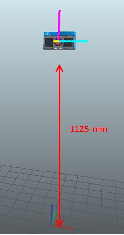
5. If the elevation of the scanner is 1125 mm, then place the floor 1125 mm away. This is entered in the Z value.
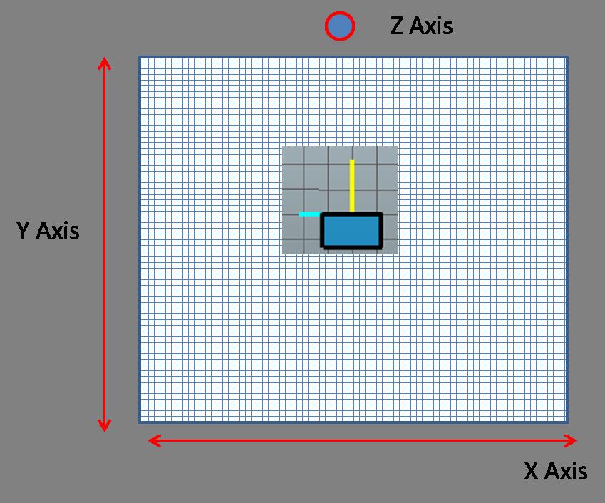
6. See the chart below for grid coordinate positions. Z axis is a top down view.
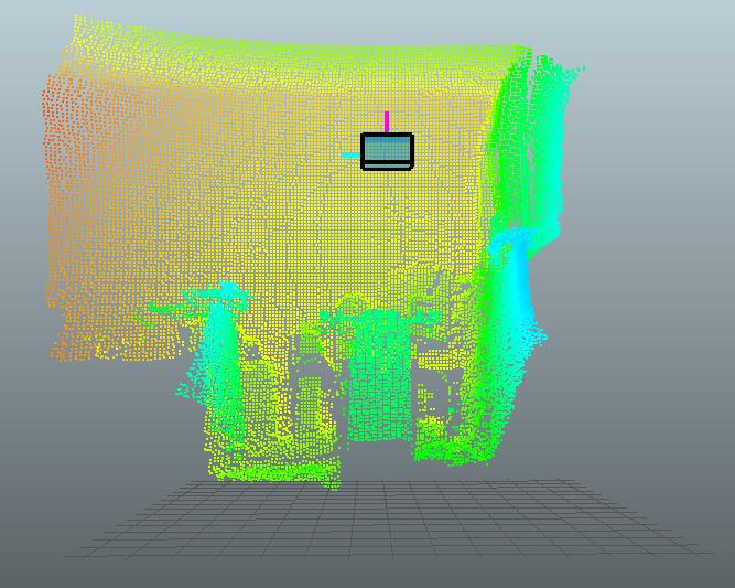
7. Select “Distance” for the 3D live camera view.
8. The following image shows the 3D view of the grid placed on the floor relative to the scanner’s centerline.
How to Measure Objects
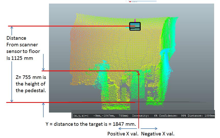
Once you’ve established the height reference, you can now measure other objects.
In the example below, the distance from the sensor to the floor is 1125 mm. Z refers to the height of the pedestal, and Y refers to the distance to the target.
How to Determine the Object Resolution
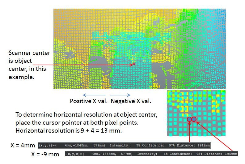
To determine horizontal resolution at the object center, place the cursor pointer at both pixel points. In this example, the horizontal resolution is 9 mm + 4 mm = 13 mm.
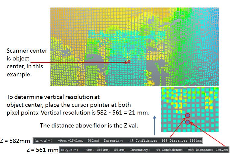
To determine the vertical resolution at the object center, place the cursor pointer at both pixel points. In this example, the vertical resolution is 582 mm – 561 mm = 21 mm.
Download the PDF version of these instructions: Visionary-T Help Guide

